

Ham radio antenna simulator
Move a slider. Watch the antenna answer.
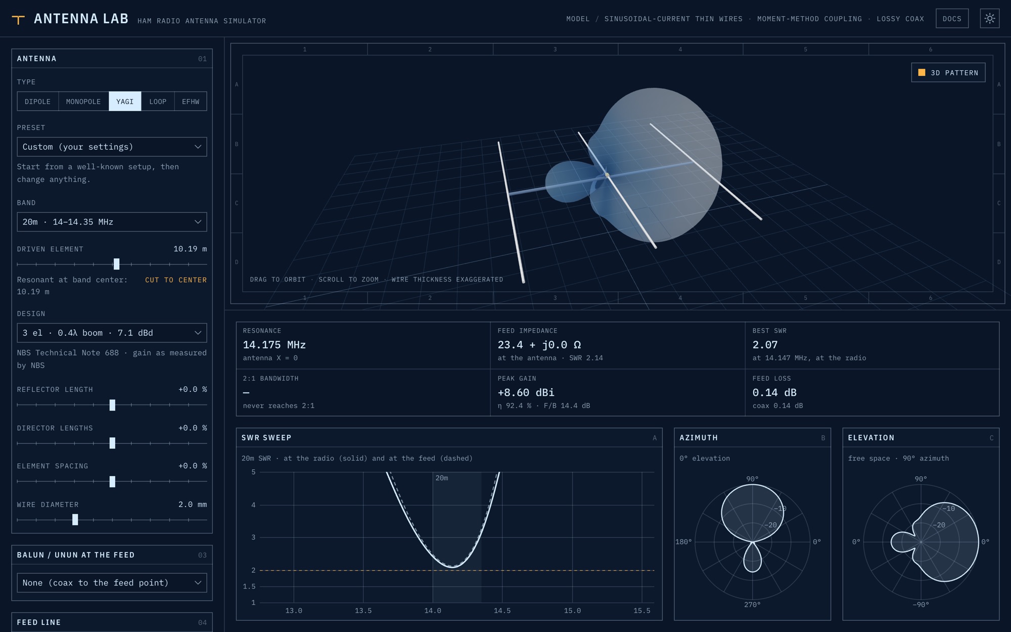
Choose an antenna, change its geometry, ground, balun and feed cable, and see the 3D model, radiation pattern, feed-point impedance and SWR sweep update as you move each control. On the web, and as iOS and Android apps built from the same code.
- Antenna types
- 5
- dipole · monopole · Yagi · loop · EFHW
- Presets
- 23
- well-known setups, ready to tweak
- Bands
- 160 m – 70 cm
- ITU Region 2, plus CB 11 m
- Yagi solver
- MoM
- method of moments, checked against NEC-2
01 / Antennas
Five antenna families, 23 presets.
Start from a well-known setup, such as an 80 m inverted V with K9YC's choke, an NBS Yagi, a 1 m magnetic loop or a mobile whip, then change anything. Choosing a band re-cuts the antenna for the band center.
| Antenna | Variants | Adjustable |
|---|---|---|
| Dipole | Flat dipole, inverted V, coil-loaded short dipole | Length, arm droop, wire diameter, loading coil (position, inductance, Q) |
| Monopole | Perfect ground, radials on average soil, elevated ground plane, coil-loaded short vertical | Height, radial count and droop, wire diameter, loading coil, base shunt-coil match |
| Yagi-Uda | NBS designs with 3, 5, 6 and 12 elements | Driven element, reflector and director lengths, element spacing and diameter |
| Loop | Full-wave square, circle and delta; small magnetic loop | Perimeter, shape, tuning capacitor, conductor diameter |
| End-fed half-wave | Half-wave wire through a 49:1 unun | Wire length, wire diameter, unun construction |
02 / Feed system
The whole chain, from the radio to the wire.
Antennas don't live alone. Every model includes what sits between it and the radio, so the SWR you read is the one your radio would see.
-
Balun or unun
1:1 current choke, 4:1 Guanella, 4:1 Ruthroff, 9:1 or 49:1. Built from a ferrite mix, toroid, cores, turns and winding line, with loss, core heating and choking impedance.
-
Feed cable
0–100 m of RG-213/U. The coax transforms the impedance, adds loss, and makes the SWR at the radio look better than at the antenna.
-
SWR sweep
At the radio, with the feed-end curve dashed when a cable is fitted. Zoom to 0.01 % of the band center; the chart re-sweeps at full resolution.
-
Readouts
Resonance, feed impedance, best SWR, 2:1 bandwidth, peak gain with radiation efficiency, and feed loss split into coil, balun and coax.
-
Radiation pattern
A 3D lobe on the model, plus azimuth and elevation polar cuts in dBi on a 30 dB scale.
-
Loading coils
Halve an element and tune a coil to resonate it, with the inductance, turn count and coil loss shown.
03 / The maths
Every formula is published.
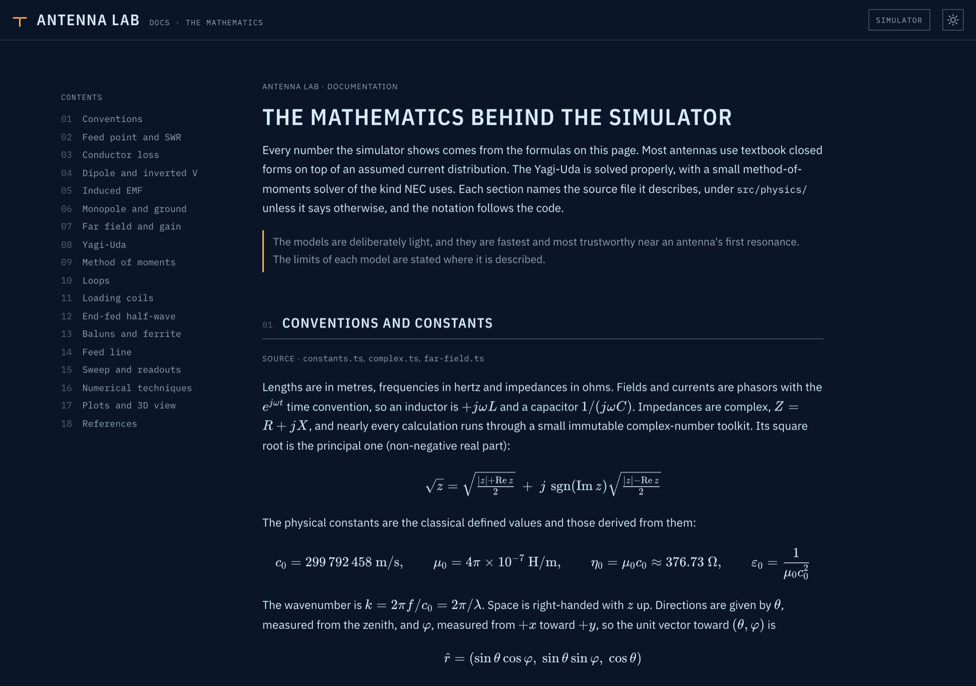
Most antennas use textbook closed forms on top of an assumed current distribution. The Yagi is solved properly, with a small method-of-moments solver of the kind NEC uses, and its results are checked against NEC-2. The app ships its own documentation: every formula and numerical technique, with the limits of each model stated where it is described.
04 / Platforms
One codebase. Web, iOS, Android, offline.
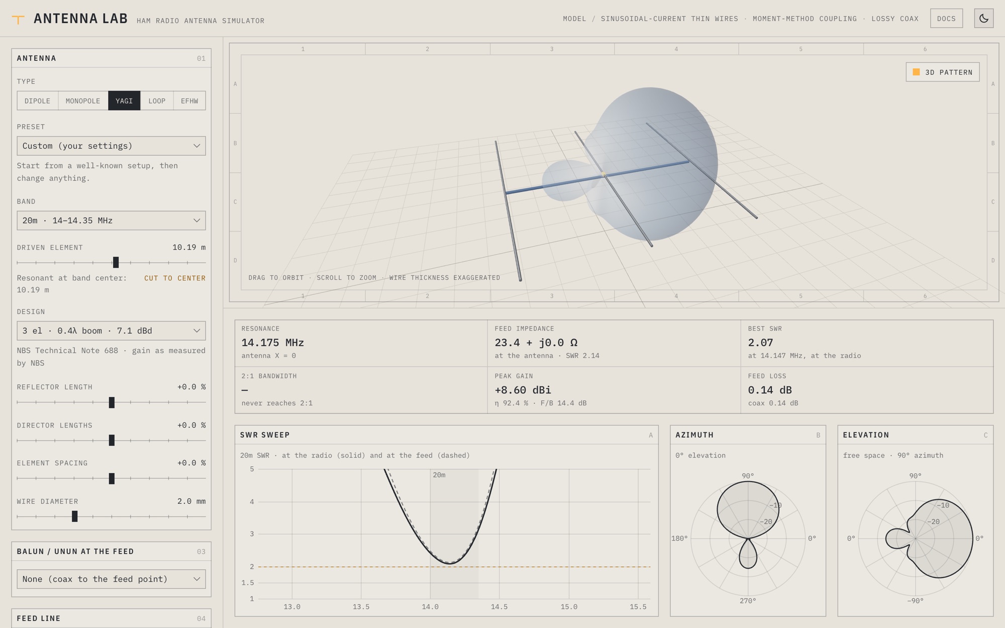
Antenna Lab is a progressive web app: install it from the browser and, after the first visit, it runs in the field with no signal. The iOS and Android apps are Capacitor shells around the same build, so the physics, charts and 3D view are identical everywhere. A dark blueprint sheet and a light paper sheet are one tap apart.
- Web
- Installable PWA, cached on the device for offline use
- iOS
- iPhone and iPad, iOS 15 and later
- Android
- Android 7.0 and later; tablet layout from 720 px
- Touch
- Tap or drag to read the SWR curve, pinch to zoom the band
Built with
- TypeScript
- three.js
- Vite
- Tailwind CSS
- KaTeX
- Vitest
- Capacitor 8
- Service worker (PWA)